Come… importare un modello BFEM
CSE è in grado di importare sia modelli fatti in SARGON che modelli fatti in SAP2000. Inoltre, qualsiasi casa produttrice di programmi agli elementi finiti che lo desideri può implementare nel proprio software la scrittura di opportuni file nel formato aperto “Open Sargon”, leggibile da CSE (file .sr3, .ddb, .sdb e .rdb). Le istruzioni in inglese per la scrittura di tale file sono scaricabili liberamente all’indirizzo http://www.castaliaweb.com/ita/P/CSE/interface.asp (in inglese). In questo modo qualsiasi software house che voglia interfacciarsi con CSE è in grado di farlo, con un modestissimo sforzo di implementazione. Qualora il produttore di un software non intenda interfacciarsi con CSE, l’utente di quel programma può implementare da sé il file di scambio, se è in grado di programmare, o eventualmente affidarsi a terzi.
I seguenti formati sono supportati da CSE:
•Formato aperto binario (.sr3)
Per importare un modello fatto con SARGON© (http://www.castaliaweb.com/ita/P/SR/home.asp) in CSE occorre dapprima creare un nuovo modello con il comando Nuovo. Dopo aver fatto questo si importa il modello Sargon (file con estensione .wsr) con il comando Importa modello BFEM. Analoga operazione va compiuta per importare un modello SAP2000, solo che occorre specificare un file di formato .SDB.
E’ da notare che prima di importare il modello questo dovrà essere stato trattato in Sargon o in Sap2000 in modo da definire tutti i segni di connessione necessari, al fine di ridurre o evitare del tutto jnodi tangenti o cuspidali. In altre parole, là dove sono presenti elementi che si intersecano in continuità occorrerà specificare quale degli elementi ininterrotti sia effettivamente privo di connessioni (elemento master). In caso contrario, uno o più nodi saranno marcati tangenti o cuspidali nella successiva fase di riconoscimento automatico (e ciò creerà ambiguità o impossibilità di soluzione).
Dalla versione 9.10 Sargon supporta il trasferimento diretto a CSE del modello attivo.
IMPORTARE .SDB (modelli Sap2000)
versioni da gennaio 2010
Sargon / CSE dà la possibilità di importare modelli preparati in Sap2000. Oltre ad importare il modello Sargon / CSE è anche in grado di importare, convertendoli, i risultati della analisi fatta in Sap2000. L'interfacciamento tra Sargon e CSE e Sap2000 è stato fatto con la collaborazione di CSI Italia.
Generalità
L'interfacciamento tra Sargon e CSE e Sap2000 può avvenire facendo leggere a Sargon o CSE un modello .SDB disponibile in una certa cartella. Eseguito il comando occorre specificare la versione di Sap 2000 con cui si vuole aprire il file.
Il modello Sap2000 ha estensione .SDB e ciò pone già un qualche problema poichè Sargon utilizza la stessa estensione per i file binari di output contenenti gli sforzi (Stress DataBase). Sarà dunque necessario ed opportuno evitare la sovrapposizione dei nomi tra il modello Sargon (.WSR e .SDB in output) ed il modello Sap2000 (.SDB). Al fine di evitare possibili sovrascritture di file importanti, quando Sargon importa un modello Sap 2000 denominato ad esempio "MODELLO.SDB", proporrà di salvarlo con il nome "MODELLO___.WSR", in modo che in seguito, in fase di solving, venga creato il file "MODELLO___.SDB" non quindi sovrapposto al file "MODELLO.SDB" originario. Analoga procedura avviene in CSE, quando viene direttamente letto e importato un file .SDB (Sap2000). In questo caso il modello CSE si chiamerà "MODELLO___.CSE" e quindi anche in questo caso la eventuale creazione dei file binari di output delle azioni interne (SDB) non creerà alcuna sovrapposizione.
L'importazione di un file SDB (Sap2000) da parte di Sargon o di CSE richiede che sul computer sia presente una installazione funzionante di Sap2000, con la relativa chiave di protezione. In effetti, l'importazione di un file di Sap2000 comporta l'esecuzione in background di Sap2000 stesso e il link tra la dll di Sargon/CSE "sarkern.dll" con il medesimo Sap2000.exe.
Appena eseguito il comando, il programma Sargon o CSE chiede se si vuole eseguire il solving del modello usando Sap2000. La richiesta serve ad eseguire l'analisi in Sap2000, al fine di disporre, se necessario, dei risultati della analisi, così come calcolati da Sap 2000. Se si risponde di sì, Sap2000 eseguirà immediatamente dopo il solving e quindi i risultati saranno resi disponibili per le successive elaborazioni. Se si risponde di no si danno due casi. Se il solving non è mai stato eseguito allora i risultati di Sap2000 non saranno disponibili, e quindi non potranno essere importati. Se il solving è già stato eseguito in precedenza allora i risultati sono disponibili.
Dopo questa domanda la routine di conversione fa un'altra domanda: viene chiesto se si vogliono importare in Sargon (o in CSE) i risultati del solving di Sap2000. Se si risponde di no i risultati della elaborazione (spostamenti, azioni interne) non verranno importati. In Sargon ciò comporta il fatto che il modello importato non avrà disponibile il post-processing: l'analisi si dovrà fare usando i solutori di Sargon stesso. In CSE ciò comporta la perdita della possibilità di usare i calcoli fem come base per il calcolo delle connessioni, e quindi si potranno usare solo le combinazioni non derivanti da un calcolo FEM.
Se si decide di importare i risultati di Sap2000 all'interno di Sargon o di CSE, la routine di conversione si occupa di fare le seguenti cose:
1.Creare un file binario .DDB contenente gli spostamenti di tutti i nodi in tutti i casi di carico;
2.Creare un file binario .SDB contenente le azioni interne e gli sforzi di tutti gli elementi in tutti i casi di carico;
3.Creare un file binario .RDB contenente le reazioni vincolari di tutti i nodi in tutte le condizioni di carico;
4.Marcare il modello come "risolto" al fine di consentire l'accesso ai dati contenuti nei file binari medesimi.
Nel seguito saranno dati chiarimenti su specifici punti relativi alle principali problematiche incontrate nel corso della scrittura della procedura di conversione.
Conversione di Forme sezionali
Prima ancora di aprire e leggere il modello da importare la routine di conversione legge ed importa le forme sezionali in modo da stabilire una opportuna corrispondenza tra le forme sezionali in Sargon/CSE e le forme sezionali in Sap2000.
•Il file di corrispondenza tra le forme sezionali di Sargon e quelle di Sap2000 di chiama "WSR_S2K_SHPCVT.TXT" e risiede nella cartella di installazione di Sargon. Tale file verrà usato nel caso in cui si importi un modello Sap2000 all'interno di Sargon.
•Il file di corrispondenza tra le forme sezionali di CSE e quelle di Sap2000 di chiama "WSR_S2K_SHPCVT.TXT" e risiede nella cartella di installazione di CSE. Tale file verrà usato nel caso in cui si importi un modello Sap2000 all'interno di CSE.
Il file, che di solito è il medesimo per Sargon e CSE, è organizzato in questo modo e prende il nome di "file di corrispondenza".
$
$
$
IPE 100 IPE100
IPE 120 IPE120
IPE 140 IPE140
IPE R 140 IPE140R
IPE 160 IPE160
Nella prima colonna compaiono i nomi dei profili nell'ambiente Sargon/CSE. Nella seconda colonna, ordinatamente riga per riga, compaiono i corrispondenti nomi dei profili in Sap2000. Il riconoscimento di un profilo viene eseguito per mezzo del nome. Se al nome "beta" in Sap 2000 corrisponde il nome "alfa" in Sargon/CSE, allora la forma sezionale "alfa" sarà fatta corrispondere a quella "beta". Per poter conoscere le caratteristiche della forma sezionale "alfa" il programma deve aprire un archivio di forme sezionali di tipo .SMA (un file .SMA) e precisamente:
•se si sta usando Sargon il file "sargon.sma" contenuto nella cartella del programma Sargon;
•se si sta usando CSE il file "cse.sma" contenuto nella cartella del programma CSE.
Se in prima riga del file di corrispondenza compare un "$" o "\\" allora la riga è un commento.
I nomi vengono comparati per i loro primi 18 caratteri. Affinché due nomi vengano riconosciuti deve esservi perfetta corrispondenza in tutti i 18 caratteri.
Le regole seguite dalla routine di conversione sono precisamente le seguenti:
1.Vengono lette le forme sezionali del file .SMA pertinente al programma che si sta usando (Sargon o CSE).
2.Viene letto e tenuto in memoria l'intero file di conversione con le due colonne di nomi.
3.Vengono letti i profili all'interno del modello Sap2000 e questi vengono trasformati in profili di tipo Sargon/CSE con queste regole.
a.Se ilprofilo è del tipo ad I e non è stato originariamente letto da un archivio viene convertito in un profilo ad I saldato avente le stesse quote del profilo in Sap2000 (si noti che i profili ad I non hanno, in Sap2000, il raggio di raccordo definito, e quindi non si saprebbe come convertirli in profili del tipo H laminato in Sargon/CSE). In questo caso non si usa il file di conversione precedentemente nominato. Se invece il profilo è ad I ed è stato letto originariamente da un archivio, allora il suo nome d'archivio viene cercato nella seconda colonna del file di conversione. Se non viene trovato allora, per evitare di scartarlo,il profilo viene convertito usando le quote come profilo saldato. Se invece viene trovato, allora il nome del profilo corrispondente, nella prima colonna, viene cercato nell'archivio .SMA. Se viene trovato questo nome nel file .SMA allora il profilo Sap2000 viene convertito con quello trovato nel file .SMA. Se non viene trovato nel file .SMA allora viene fornito un messaggio di errore ( a cui si potrà ovviare semplicemente aggiungendo all'archivio .SMA un profilo con il nome corrispondente), e la conversione viene comunque fatta come profilo saldato usando le dimensioni disponibili (H, B, tw, tf). Si noti che ai fini delle verifiche è diverso usare profili laminati o saldati. Si consiglia quindi di convertire i profili usando sempre il file di conversione.
b.Analoga procedura viene seguita per i profili a C, T, L, box.
c.I profili pipe, rettangolari e circolari pieni vengono comunque importati dato che le loro quote sono note (senza cercarli nel file di conversione, non è infatti necessario).
d.I profili "SECTION_GENERAL" vengono cercati nel file di conversione. Se sono trovati vengono convertiti se no vengono trasformati in sezioni "generiche" delle quali si danno il nome e le proprietà di calcolo (area, momenti di inerzia).
e.I profili "angolari doppi"e "a C doppi" vengono cercati nel file di conversione e se non sono trovati viene dato un messaggio di errore.
f.I profili "a C formati a freddo" e "a Z formati a freddo", "a omega formati a freddo" vengono convertiti usando le quote.
g.I profili "a doppio C formato a freddo", "a L formato a freddo" e a "doppio L formato a freddo" non vengono convertiti in quanto non ci sono le routine API per farlo.
h.I profili "SD" (Section Designer) vengono cercati nel file di conversione.
i.I profili "SECTION_VARIABLE", "SECTION_JOIST", "SECTION_BRIDGE" non sono importati.
j.Altri profili non sono supportati e non vengono importati. La loro presenza genera un messaggio di errore.
Il file di conversione può essere gestito facilmente dall'utente e possono essere aggiunte le righe che si vuole, liberamente.
Al Gennaio 2010 il file di conversione contiene circa 4000 profili. Sono contenuti profili HEA, HEB, HEM, IPE, ILS, HLS, H, L, UPN, L accoppiati, UPN accoppiati, RHS, tubi, eccetera eccetera.
E' bene osservare che qualsiasi utente può sempre stabilire la corretta conversione tra una forma sezionale in Sap2000 ed una forma sezionale in Sargon CSE semplicemente sincerandosi che la forma desiderata sia presente nell'archivio .SMA e che la corrispondenza tra i nomi dei due profili Sargon/CSE-Sap2000 sia presente nel file di corrispondenza. Il lavoro fatto una volta varrà naturalmente ogni volta che quei profili, magari di tipo speciale, verranno usati in qualsivoglia modello.
Nel corso della installazione degli aggiornamenti, al fine di evitare la sovrascrittura dei propri file di corrispondenza, e dei propri archivi SMA, si raccomanda di eseguire una copia di salvataggio sia del file di corrispondenza, sia del file SMA.
Conversione di materiali
Vengono letti e importati i materiali isotropi ed i materiali "uniaxial". Non vengono importati i materiali ortotropici ed anisotropici.
Conversione di casi di carico e di combinazioni
In Sap2000 ci sono Load Case e Load Patterns. I LoadCases di Sap2000 vengono fatti corrispondere ai Load Cases (Casi di Carico) in Sargon / CSE. Generalmente il numero dei Load Cases in Sap2000 coincide con il numero dei Load Cases in Sargon (a meno che non vengano scartati i Load Cases di Sap 2000 che non trovano corrispondenza analoga in Sargon come le analisi modali, che Sargon non gestisce come Load Case). Poichè in Sap 2000, in generale, i Load Cases possono essere costituiti da sovrapposizioni di Load Patterns, analoga sovrapposizione si avrà nel Load Cases di Sargon/CSE, con la differenza che dei Load Patterns non rimarrà traccia in Sargon /CSE.
Il tipo dei Load Cases in Sargon sarà eguale al tipo dell'ultimo Load Pattern riversato nel Load Case. Di solito ai Load Patterns corrispondono identici Load Cases (1 Load Pattern per 1 Load Case), ma se questo non fosse, vale la regola che il tipo del Load Case in Sargon è il tipo dell'ultimo Load Pattern ivi definito. A sua volta il tipo del Load Pattern in Sap 2000 corrisponde al tipo del Load Case in Sargon /CSE secondo la seguente tabella:
Load Patterns (Sap 2000) |
Load Case (Sargon) |
DEAD |
DEAD |
SUPER DEAD |
DEAD |
LIVE |
LIVE |
REDUCE LIVE |
LIVE |
QUAKE |
EARTHQUAKE |
WIND |
WIND |
SNOW |
SNOW |
OTHER |
LIVE |
MOVE |
LIVE |
TEMPERATURE |
THERMAL |
ROOF LIVE |
LIVE |
NOTIONAL |
DEAD |
PATTERN LIVE |
LIVE |
WAVE |
LIVE |
BRAKING |
LIVE |
CENTRIFUGAL |
LIVE |
FRICTIONAL |
LIVE |
ICE |
SNOW |
altri |
LIVE |
Il tipo del Load Case in Sap 2000 è riferito al tipo di analisi: statica, nonlineare, modale, spettro di risposta, ecc.. Vengono importati:
1.I load case statici lineari
2.I load case statici non lineari
3.I load case di tipo risposta allo spettro
In Sargon i load case di tipo "analisi modale" non vengono importati perchè hanno un differente tipo di codifica, le modali vengono gestite a parte.
Vengono importati all'interno di Sargon/ CSE i seguenti possibili carichi:
•Forze nodali
•Coppie nodali
•Carichi distribuiti (forze o coppie) su elementi frame, sistema di riferimento globale o locale (nota: in Sap2000, anche in presenza di eccentricità su un elemento, il carico distribuito viene comunque applicato sulla lunghezza da nodo a nodo, senza tenere in conto dell'eccentricità)
•Carichi concentrati (forze o coppie) su elementi frame, sistema globale o locale
•Carichi gravitazionali su elementi frame
•Carichi di peso proprio definiti moltiplicatori del peso proprio all'interno dei load patterns
•Carichi termici su elementi frame
Non sono al momento gestiti i carichi gravitazionali sugli elementi plate-shell e sui solidi, né i carichi termici sugli stessi.
In Sap 2000 ci sono vari tipi di combinazioni, che possono essere combinazioni di casi di carico e/o di altre combinazioni. Vengono importate in Sargon / CSE:
•Le combinazioni di tipo "linear additive";
•Le combinazioni di tipo "envelope";
•Le combinazioni di tipo "absolute additive";
•Le combinazioni di tipo "SRSS";
•Le combinazioni di tipo "range additive".
Le combinazioni vengono aggiunte al Combi Set attivo in Sargon / CSE.
Conversione di elementi
Non tutti gli elementi definiti in Sap 2000 possono essere importati in Sargon / CSE e viceversa.
Di seguito si dà conto di quali elementi vengano importati e quali no.
1.Elementi frame in Sap 2000
a.vengono importati sempre come elementi beam (trave) in sargon. Sono importati gli svincoli, l'orientazione della terna locale, gli offset rigidi, le rigidezze in caso di "fissità parziale" nel caso di molle associate ai momenti flettenti (mentre vengono scartate le molle relative ad eventuali fissità parziali in senso assiale, torsionale e tagliante).
b.vi è una diversa convenzione sugli assi locali tra Sap2000 e Sargon / CSE. In particolare vale la seguente tabella di conversione:
Asse |
Di Sargon diventa |
Di Sap 2000 diventa |
1 |
1 |
1 |
2 |
-3 |
3 |
3 |
2 |
-2 |
c.Se sono curvi, gli elementi frame non vengono importati in Sargon / CSE
2.Elementi plate in Sap 2000. Sono elementi privi di rigidezza membranale. Come tali non esistono in Sargon. Vengono quindi convertiti in elementi plate-shell di Sargon con rigidezza membranale data dallo spessore definito nella proprietà di area.
3.Elementi shell (plate+membrana) in Sap 2000. Sono importati tutti i tipi di shell (sottile, spesso) ad eccezione dello shell multistrato (layered, type=6).
4.Elementi membrana in Sap 2000. Vengono convertiti in elementi membrana di Sargon / CSE.
5.Elementi solidi in Sap 2000. Vengono convertiti in elementi solidi in Sargon / CSE.
6.Elementi ASOLID in Sap 2000. Non vengono convertiti.
7.Elementi CABLE in Sap 2000. Non vengono convertiti.
8.Elementi LINK / SUPPORT in Sap 2000. Non vengono convertiti.
9.Oggetti TENDON in Sap 2000. Non vengono convertiti.
10.Oggetti PLANE in Sap 2000 (plane strain, plane stress). Non vengono convertiti.
Conversione dei segni di connessione
All'interno di Sargon si fa uso del segno di connessione per indicare membrature che, pur essendo staticamente in continuità sul nodo, devono essere considerate costruttivamente interrotte. Elementi frame che posseggano un qualche tipo di end-release sono considerati automaticamente interrotti, e quindi non è necessario apporre alcun segno di connessione. Il problema invece si pone per quegli elementi che, pur non avendo alcun end-release, devono essere considerati interrotti al fine di ricercare i jnodi eguali ed i renodi in CSE.
Dato che le informazioni "normali" gestite da Sap 2000 non consentivano di passare esplicitamente questa informazione, si è provveduto a predisporre una opportuna codifica, che, utilizzando il concetto di "gruppo" presente in Sap 2000, fosse utile a far passare le informazioni desiderate.
Un elemento frame può avere un segno di connessione ad un estremo, all'altro o a tutti e due. Come già detto, se ad un estremo è presente un end release allora non è necessario aggiungere un segno di connessione perchè è implicito.
In Sap 2000 si potranno aggiungere i seguenti gruppi:
"BI"
"BJ"
"BIBJ"
Tutti gli elementi frame che appartengono al gruppo "BI" hanno l'estremo "I" con segno di connessione;
Tutti gli elementi frame che appartengono al gruppo "BJ" hanno l'estremo "J" con segno di connessione;
Tutti gli elementi frame che appartengono al gruppo "BIBJ" hanno entrambi gli estremi con segno di connessione.
Conversione dei risultati (post processing)
Come detto nel caso in cui siano disponibili i risultati della analisi di Sap 2000, la routine di importazione è in grado di creare i file binari con i risultati nel formato di Sargon / CSE. Vengono importati:
1.Tutti gli spostamenti di tutti i nodi in tutti i casi di carico;
2.Tutte le reazioni vincolari di tutti i nodi in tutti i casi di carico;
3.Tutte le azioni interne degli elementi frame (convertiti in beam) in tutti i casi di carico.
Al momento gli sforzi degli elementi bidimensionali e solidi non sono importati e quindi risulteranno nulli.
versioni da ottobre 2012
(questo argomento è solo in inglese)
Sargon/ CSE offers the ability to import models prepared in STRAP. As well as importing the model, Sargon/ CSE can also import and convert the results of the analysis carried out in STRAP.
General introduction
In order to start the conversion from STRAP file format to CSE or SARGON file format, the user must choose a .dat file which identify the model. In the subfolder where the model files are written, there may be several other STRAP models, so choosing the .DAT of the model we are interested in, simply works to define the model number we are interested in.
The file importing feature works by the following logical path:
1) Ask to STRAP to create a report file for the model at hand, with a suitable file format.
2) Read the report file created by STRAP and convert it into a CSE or SARGON file.
As phase 1 requires STRAP STBATCH.EXE, an installed and working copy of STRAP must be available in the computer, including the relevant protection key. Sargon/CSE automatically creates the run file and the report file format required by STBATCH.exe to print the report, and automatically runs STBATCH itself. In order to run STBATCH, the STRAP folder must be known to the program CSE/SARGON which performs conversion. It is initially assumed that STRAP is in "C:\STRAP1" folder. If this is true (a copy of STRAP is found in that folder) the program moves on, without asking further information. If there is not an available copy of STRAP in "C:\STRAP1" folder, the program looks for the environment variable named "STRAPFOLDER". This environment variable may be set once for all by the user in order to teach CSE/SARGON where to find STRAP. In order to set an environment variable just go to Control Panel, choose Security and System, System, Advanced Settings, and choose "Environment variables". A dialog will appear, choose "New". Set as the name of the variable "STRAPFOLDER" and as "value" the folder where actually STRAP is, e.g. "C:\STRAPNEW". If the environment variable is found, the program will run STBATCH in the folder specfied by the environment variable. If the environment variable does not exist, then the program will ask the user to input the folder where STRAP is placed, issuing a warning that such input may be avoided by properly setting the environment variable STRAPFOLDER.
Report file will be named CSE*.DAT (if using CSE, or WSR*.DAT if using Sargon). Its format has been prepared to be read by Sargon/CSE. So, when GEOM001.DAT is imported in CSE, STBATCH.EXE will print CSE001.DAT, in the same folder of STRAP model. Then CSE will automatically import CSE001.DAT, creating a CSE001.CSE model and its related results files (CSE001.DDB, CSE001.SDB and CSE001.RDB, for displacements, stresses/forces and constraint reactions). User can choose a different name for CSE (or Sargon) model.
Some specific aspects of the main issues encountered when writing the conversion procedure are discussed in more detail below.
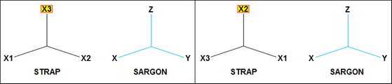
Converting global axes
Before reading STRAP's report file, CSE asks the user if vertical global axis in STRAP model is X2 or X3. According to user's choice, one of the following correspondences will be assumed (STRAP's vertical axis is highlighted).
Converting materials
Since some information about materials is missing in STRAP (steel yield stress, for example) when the model is imported user can choose to apply one of the materials from CSE/Sargon.sma archive or define missing properties (yield stress and ultimate stress) one by one. After the importing, user can change or modify materials for desired elements, if needed.
Converting cross-sections
Before opening and reading the model which is to be imported, the conversion routine reads and imports the cross-sections needed in order to establish a suitable match between the sectional forms in Sargon/CSE and those in STRAP.
The mapping file between CSE and STRAP cross-sections is called "WSR_STRAP_SHPCVT.TXT" and can be found in the CSE installation folder. This file will be used when a STRAP model is imported into Sargon/CSE. This file, known as the "mapping file", is usually the same for Sargon and CSE, and is structured as shown below.
$
$
IPE 100 IPE&100
IPE 120 IPE&120
IPE 140 IPE&140
IPE 160 IPE&160
...
The first column lists the names of the sections in the Sargon/CSE environment.
The second column lists the corresponding section names in STRAP. This is build by adding three strings: 1) the string referred to the kind of the cross-section; 2) the letter "&"; 3) the cross-section name in STRAP (which has no kind attached).
A section is identified by its name. If the name "beta" in STRAP corresponds to the name "alpha" in Sargon/CSE, then the sectional form "alpha" will be mapped to "beta". To find out the properties of the sectional form "alpha", the program must open an archive of sectional forms of type .SMA (an .SMA file); in particular:
•if CSE is being used, the file is "cse.sma" in the CSE program folder.
•if Sargon is in use, this will be the file "sargon.sma" in the Sargon program folder;
If the first line of the mapping file contains a "$" or "\\" symbol that means it is a comment line.
The first 18 characters of the names are used for matching purposes. For two names to be matched, each of these 18 characters must be identical.
The conversion file is easy to manage and the user can add any lines they require. The user may actually wish to edit the file "WSR_STRAP_SHPCVT.TXT" in order to add more conversion lines. So, if a cross-section used in a STRAP model has not been automatically detected by conversion program, the User may whish ad add the section in CSE.SMA archive by using SAMBA program, and then edit the conversion file, establishing a match between the STRAP cross section and the new cross-section just added into the CSE.SMA archive by using SAMBA.Conversion file includes sections from European, British, American and Indian archives. As at October 2012, the conversion file contained around 2,000 sections (Europe, UK, US, India).
The conversion routine operates according to the following detailed rules:
1.The cross-sections in the .SMA file relevant to the program in use (Sargon or CSE) are read.
2.The entire conversion file is read into memory with its two columns of names.
3.The sections in the STRAP model are read and then transformed into Sargon/CSE-type sections following the procedure below.
A.The following sections are read by using their dimensions (no conversion file used): rectangular (property type, PT, =1); pipe (PT=2); tube (PT=3); L (PT=4); I (PT=5); [ (PT=6); T (PT=7), circle (PT=8).
B.If property type is equal to -1, the cross section is read from table, and conversion file will be used. If the cross-section is of the types "><", "2L", "[]", "][", the program decodes the name of the simple cross-section, and searches this cross-section in the conversion table. The complex cross section will be rebuild using simple cross-section and the distance between the two cross sections. The simple cross section name is found by performing the following tasks. If the string "><" is followed by "L130x90x12", in STRAP report file, the program should rebuild the proper cross section name in the second column of conversion file. To do that, "L130x90x12" must be replaced by "L&130x90x12". The keyword kind "L" must then be searched for and separated by size. So for angles the program searches for the following possible keywords: "L"; "E.ANGLES"; "U.ANGLES". For channels the program searches the following possible keywords: "UNP"; "UAP"; "CHANNELS".
C.Some sections are not supported and are not imported: if detected, they are replaced with a rectangular fictitious shape in order to complete the importing. User can then assign the desired shape defining it directly in CSE, without loss of results. Otherwise, user can add the needed sections to Sargon/Cse.sma archive and adding the related conversion lines in WSR_STRAP_SHPCVT.TXT.
It is as well to note that any user can always ensure that a sectional form in STRAP is converted correctly to a sectional form in Sargon/ CSE, simply by satisfying themselves that the desired form is present in the .SMA archive and that the Sargon/CSE-STRAP mapping between the names of the two sections is available in the mapping file. Once carried out, the work will of course apply every time those sections are used in any model in the future.
When installing upgrades, in order to avoid overwriting your mapping files and SMA archives, it is advisable to take a backup copy of both the mapping file and the SMA file.
When two non standard cross sections are matched (CSE/SARGON archive versus STRAP) it is important to check that the principal axes of the cross-sections are the same.
Converting load cases and combinations
STRAP prints results in the report for combinations only. For this reason, in addition to "true" combinations, user must define n "fictitious" combinations, one for each load case. A combination is automatically recognized as "fictitious" by CSE if it contains a multiplication factor equal to 1.0 for one load case only, and 0.0 for all the other load cases (for example, combination = 1.0 * case1 + 0.0 * case2 + 0.0 * case3 + 0.0 * etc.). See the example in the following table (fictitious combinations can be also at the end of the list, their position is not relevant); n is the number of load cases (and of fictitious combinations), m is the number of true combinations.
|
load case 1 |
load case 2 |
... |
load case n |
combi 1(fictitious) |
1 |
0 |
... |
0 |
combi 2 (fictitious) |
0 |
1 |
... |
0 |
... |
... |
... |
... |
... |
combi n (fictitious) |
0 |
0 |
0 |
1 |
combi n+1 (true) |
desired factors for each load case |
|||
combi n+2 (true) |
||||
... |
||||
combi n+m (true) |
||||
Combinations are added to the active Combi Set in Sargon/ CSE. Fictious combinations will not be selected and so they will not be used in CSE checks.
Note that STRAP does not print applied loads in the report; only results are available (see below).
Converting elements
Not all the elements defined in STRAP can be imported into Sargon/ CSE.
A discussion of which elements are imported and which are not follows below.
1.Beam elements in STRAP
a)Orientaton, end releases and rigid offsets are read by conversion program.
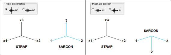
b)Local orientation conversion from STRAP to Sargon/CSE depends on user's choice about major axis definition in STRAP. See the following conversion cases:
c)Tapered beam elements are not supported in Sargon/ CSE.
2.Plate elements in STRAP.
a.Elements with 3 or 4 nodes are read by conversion routine.
b.All elements are assumed to be thin plates with constant thickness.
c.No release of edge is currently supported (nor would be useful in CSE).
3.Solid elements in STRAP.
a.Elements with 4 6 or 8 nodes are read by conversion routine.
4.Spring elements in STRAP.
a.Spring elements are read by conversion routine.
b.Spring direction must be specified in global reference system, i.e. node system in spring definition must be 0.
c.For each stiffness not null, a spring (rotational or translational) is added in CSE/Sargon.
Converting connection codes
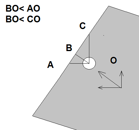
Connection codes are not supported by STRAP, and it was not possible to use conventions to make Sargon/CSE able to assign needed connection codes (as done for SAP2000, for example, where conventional groups define connection codes on beam elements extremes). For this reason, user possibly needs to define connection codes in CSE after the model has been imported from STRAP and before JNODES are searched for. If end releases are left unchanged and only connection codes are added, this operation does not imply a loss of results, so imported results will be still available after connection codes definition. We recall here briefly that connection codes are useful when more elements meet in a node without any end release: connection codes will mark the elements which will be interrupted and connected, while element with no connection code will remain unmodified and will therefore be the "master" of the connection.
Converting the results (post-processing)
As already mentioned if results of the STRAP analysis are available, the import routine can create the binary files with the results in the Sargon/ CSE format. The following are imported:
1.All displacements of all nodes in all load cases and combinations
2.All constraint reactions of all nodes in all load cases and combinations
3.All internal forces at beams extremes in all load cases and combinations (at the extremes only, since internal forces along beam axis are not printed in STRAP report.
4.Currently, the stresses for two-dimensional and solid elements are not imported and are therefore null.
After the import
Since some information about the model are missing in STRAP's output report, user may need to modify the model before jnodes search: connection codes may be added to some elements to avoid cuspidal or tangential jnodes, different materials may be assigned to different elements, etc. All these operations can be done without losing the results. Note also that cross-sections can be changed (for example if a section is not in the conversion file, so replaced with a dummy one).
IMPORTING A FILE .STD (STAAD PRO)
versions from December 2012 onwards
Using Sargon or CSE you can import a model prepared in STAAD PRO, and the results got by using that program. However, as the documentation referring to Open Staad is quite lacking of several important info, several information cannot be transferred or it is not clearly explained how to do that. In the following a clear description of what is imported into Sargon/CSE will be given. All most important and needed information, however, is transferred.
Introduction
Importing a model into Sargon or CSE is a two steps procedure. First you create a text file by using STAAD. Then you import that text file using Sargon or CSE.
Let's have a model named "MODEL.STD" in a given folder. The first step is to create a text file named "MODEL.STD.TXT", in the same folder. This is done by executing a proper macro from within STAAD PRO. The macro itself is in the file "STD2STX.VBS", placed in the installation folder of Sargon (if you are using Sargon) or CSE (if you are using CSE). To execute a macro in STAAD PRO, open the model at hand, say "MODEL.STD", and run the analysis. Save results, so that they will be available for the macro. Then from the File Toolbar choose the "Run VB Macro" command, and select the file "STD2STX.VBS" located in Sargon or CSE installation folder. Then run the macro.
During the macro execution, if the results are not available you are prompted to decide if continue the execution or not. If you are not interested in post processing data, you can continue. If, on the other hand, you are interested in results (i.e. displacements, reactions, and member forces) then exit the macro ("Continue?" Answer: "No") and run the analysis.
Once the macro is executed successfully, a message will appear with the full path of the new file .STD.TXT just created. This file will be named "MODEL.STD.TXT" and is a text file with a wide subset of the information referring to you model.
Next step will be to open Sargon (or CSE) with a new blank file, and choose the command File-Import (in Sargon) or File-Import FEM Model (in CSE). Among the file types available you will find "STD.TXT (STAAD PRO)": choose that particular file format, browse your hard disk and select the file which you previously created in the model folder. This will run a command that will read the file and convert it into the Sargon (or CSE) file format.
If the user does decide to import the STAAD PRO results into Sargon or CSE, the conversion routine will:
1.Create a binary .DDB file containing the displacements of all nodes in all load cases;
2.Create a binary .SDB file containing the internal forces and stresses in all elements in all load cases;
3.Create a binary .RDB file containing the constraint reactions of all nodes in all load cases;
4.Mark the model as “solved” to make the data contained in the actual binary files accessible.
Some specific aspects of the main issues encountered when writing the conversion procedure are discussed in more detail below.
Units of measurement
File MODEL.STD.TXT is created or using [kN, meter] or using [kips, inch] units. This depends on the units used in STAAD PRO, if metric or imperial. Stresses are then given in kN/m2, and moments in kNm, or in ksi and kipin.
Z axis Up vs Y axis Up
Both Sargon and CSE use a "Z axis up" convention, so when reading a STAAD PRO file it's much better to have it created using the "Z axis up" convention as well. If Z axis up is used, then there is a perfect match between global axis (X, Y, Z) in STAAD and those in Sargon or CSE. If on the other hand the Yup flag is used in STAAD, then the conversion between global axes in STAAD and global axes in Sargon / CSE is as follows :
STAAD GLOBAL AXES |
SARGON CSE GLOBAL AXES |
X |
Y |
Y |
Z |
Z |
X |
Converting cross-section local axes
STAAD uses (x, y, z) local axes, while Sargon /CSE uses (1, 2, 3) local axes. However, generally these axes are placed differently over cross-sections, depending on the cross-section kind, and depending on the Z axis up, o Y axis up STAAD user's choice.
Generally speaking the following conversions apply for the most part of the cross sections (i.e. those doubly symmetric or with symmetry about weak axis):
STAAD MEMBER LOCAL AXES Y axis up |
SARGON CSE MEMBER LOCAL AXES |
x |
1, or x |
y |
3, or z |
z |
-2, or -y |
STAAD MEMBER LOCAL AXES Z axis up |
SARGON CSE MEMBER LOCAL AXES |
x |
1, or x |
y |
2, or y |
z |
3, or z |
Conversions adopted for the most part of the cross sections
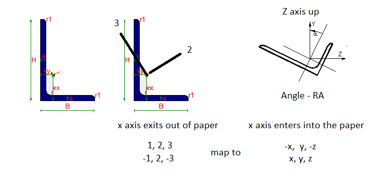
However, some sections require a different mapping, according to the following table.
STAAD MEMBER LOCAL AXES |
SARGON CSE MEMBER LOCAL AXES |
Y axis up. C cross-sections (x, y, z) |
(1, -3, 2) |
Y axis up. L cross-sections (x, y, z) |
(-1, -2, 3) |
Y axis up. L-RA (reversed axes) cross-sections (x, y, z) |
(-1, -3, -2) |
Z axis up. C cross-sections (x, y, z) |
(1, -2, -3) |
Z axis up. L cross-sections (x, y, z) |
(-1, -3, -2) |
Z axis up. L-RA (reversed axes) cross-sections (x, y, z) |
(-1, 2, -3) |
Generally speaking a right tern (x, y, z) must be transformed into another right tern (1, 2, 3), and this can be done just in 8 different ways, preserving axis 1 direction. Each of the 8 possible ways to transform STAAD tern (x, y, z) to Sargon / CSE (1, 2, 3) is mapped to a "local tern mapping code", from 1 to 8.
STAAD MEMBER LOCAL AXES |
Sargon / CSE local axes |
LOCAL TERN MAPPING CODE |
(x, y, z) |
(1, 2, 3 ) |
1 |
(x, y, z) |
(1, -3, 2) |
2 |
(x, y, z) |
(1, -2, -3) |
3 |
(x, y, z) |
(1, 3, -2) |
4 |
(x, y, z) |
(-1, 3, 2) |
5 |
(x, y, z) |
(-1, -2, 3) |
6 |
(x, y, z) |
(-1, -3, -2) |
7 |
(x, y, z) |
(-1, 2, -3) |
8 |
The following table lists the conversion from Sargon / CSE to STAAD:
Sargon / CSE local axes |
STAAD MEMBER LOCAL AXES |
LOCAL TERN MAPPING CODE |
(1, 2, 3) |
(x, y, z ) |
1 |
(1, 2, 3) |
(x, z, -y) |
2 |
(1, 2, 3) |
(x, -y, -z) |
3 |
(1, 2, 3) |
(x, -z, y) |
4 |
(1, 2, 3) |
(-x, y, z) |
5 |
(1, 2, 3) |
(-x, -y, z) |
6 |
(1, 2, 3) |
(-x, -z, -y) |
7 |
(1, 2, 3) |
(-x, y, -z) |
8 |
Given this choice, we can say that the normal coding adopted by the conversion routine is the following:
STAAD MEMBER LOCAL AXES |
LOCAL TERN MAPPING CODE |
Y axis up. Generic cross-sections (x, y, z) |
4 |
Y axis up. C cross-sections (x, y, z) |
2 |
Y axis up. L cross-sections (x, y, z) |
6 |
Y axis up. L-RA cross-sections (x, y, z) |
7 |
Z axis up. Generic cross-sections (x, y, z) |
1 |
Z axis up. C cross-sections (x, y, z) |
3 |
Z axis up. L cross-sections (x, y, z) |
7 |
Z axis up. L-RA cross-sections (x, y, z) |
8 |
Generally speaking the conversion file "MODEL.STD.TXT" is written in such a way that the preceding rules are automatically applied by the conversion routine. This is got by assigning a "local tern mapping code" "0" to the cross-section in the file "MODEL.STD.TXT" (for an example of how this code is written in the file MODEL.STD.TXT, see next section).
If on the other hand this local tern mapping code in file "MODEL.STD.TXT" is overwritten by the user and set to a different value (from 1 to 8), then the program will use the coding related to the local tern mapping code specified by the user no matter the other possible rules.
An example of conversion between Sargon / CSE and STAAD working environment
(in Sargon / CSE only axis 2 is displayed, being always axis 1 getting out of paper to the viewer, and axis 3 forming a right tern)
This may be needed if special cross sections are used, so that a correct remapping of the STAAD local tern (x, y, z) to the Sargon / CSE tern (1, 2, 3) must be specified. Imagine for instance that you have used a special, not symmetric cross section in STAAD which has axes (x, y, z) according to STAAD choices (also depending on the Yup/Zup flag).
By editing the "MODEL.STD.TXT" file, at the row referring to that cross section, you will replace the code "0" with the code you need to set up a correct mapping (x, y, z)-> (1, 2, 3).
Obviously there are a number of consequences:
•changing STAAD axis "x" to -1 means reverting the direction of the arrow related to member axial axis. This need a change in load position definition, in load axial component when defined using local axes, and in the member forces as resulting on the analysis; of course member nodes (n1, n2) will be exchanged to (n2, n1).
•changing axis (y, z) to (3, 2) means changing end releases and member forces position. Also load components, if defined in local axes must be exchanged.
•generally speaking changing a sign of an axis means changing the sign of the member loads applied using local reference system, and changing member forces got by analysis;
This procedure, however, must not be done for standard cross-sections. The conversion for such cross sections is fully automatic
Converting Sectional forms
Before opening and reading the model which is to be imported, the conversion routine reads and imports the all the possible sectional forms in order to establish a suitable correspondence between the sectional forms in Sargon/CSE and those in STAADPRO.
The mapping file between the SARGON/CSE and STAAD PRO sectional forms is called "WSR_STD_SHPCVT.TXT" and can be found in the Sargon or CSE installation folder depending on the program you are using. This file will be used when a STAAD model is imported into Sargon or CSE. This file, known as the "mapping file", is usually the same for Sargon and CSE, and is structured as shown below.
$
$
IPE 100 IPE100
IPE 120 IPE120
IPE 140 IPE140
IPE R 140 IPE140R
IPE 160 IPE160
...
The first column indicates the names of the sections in the Sargon/CSE environment. The second column shows the corresponding section names in STAAD PRO. A section is identified by its name. If the name "beta" in STAAD corresponds to the name "alpha" in Sargon/CSE, then the sectional form "alpha" will be mapped to "beta" and assigned to members. To find out the properties of the sectional form "alpha", the program must open an archive of sectional forms of type .SMA (an .SMA file); in particular:
•if Sargon is in use, this will be the file "sargon.sma" in the Sargon program folder;
•if CSE is being used, the file is "cse.sma" in the CSE program folder.
If the first line of the mapping file contains a "$" or "\\" symbol that means it is a comment line.
The first 18 characters of the names are used for matching purposes. For two names to be matched, each of these 18 characters must be identical. STAAD names begins at column 41 in mapping file.
The conversion routine operates according to the following detailed rules:
1.The sectional forms in the .SMA file relevant to the program in use (Sargon or CSE) are read.
2.The entire conversion file is read into memory with its two columns of names.
3.To each cross section in the conversion file .STD.TXT is given a name and a type. The name is a string, the type is a number. Here is a typical block of information about cross sections in a .STD.STX file:
SECTION PROPERTY
9
1 "UC356X368X129" 3 610 0 3.68600E-01 3.55600E-01 1.64000E-02 3.69824E-03 8.60067E-03 1.52612E-06 1.46000E-04 4.02000E-04 1.75000E-02 1.04000E-02
2 "UC254X254X73" 3 610 0 2.54600E-01 2.54100E-01 9.31000E-03 2.18526E-03 4.82043E-03 5.76246E-07 3.91000E-05 1.14000E-04 1.42000E-02 8.60000E-03
3 "UB533X210X82" 3 610 0 2.08800E-01 5.28300E-01 1.05000E-02 5.07168E-03 3.67488E-03 5.15182E-07 2.01000E-05 4.75000E-04 1.32000E-02 9.60000E-03
4 "UB457X152X52" 3 610 0 1.52400E-01 4.49800E-01 6.66000E-03 3.41848E-03 2.21488E-03 2.13741E-07 6.45000E-06 2.14000E-04 1.09000E-02 7.60000E-03
5 "UA100X100X8" 3 641 0 1.00000E-01 1.00000E-01 1.55000E-03 5.33333E-04 5.33333E-04 3.34507E-08 6.11001E-07 2.35265E-06 8.00000E-03 8.00000E-03
6 "UC203X203X46" 3 610 0 2.03600E-01 2.03200E-01 5.87000E-03 1.46304E-03 2.98613E-03 2.21539E-07 1.55000E-05 4.57000E-05 1.10000E-02 7.20000E-03
7 "UB406X178X67" 3 610 0 1.78800E-01 4.09400E-01 8.55000E-03 3.60272E-03 3.40912E-03 4.61117E-07 1.36000E-05 2.43000E-04 1.43000E-02 8.80000E-03
8 "UB406X140X39" 3 610 0 1.41800E-01 3.98000E-01 4.97000E-03 2.54720E-03 1.62597E-03 1.07021E-07 4.10000E-06 1.25000E-04 8.60000E-03 6.40000E-03
9 "UA60x60x5" 3 641 0 6.00000E-02 6.00000E-02 5.82000E-04 2.00000E-04 2.00000E-04 4.89583E-09 8.07088E-08 3.17448E-07 5.00000E-03 5.00000E-03
The first field is the cross section number. Then there is the cross section name. Next the cross section country. The bold numbers in the 4th field are the cross section types (in STAAD PRO). The next field is local tern mapping code (see previous section) and is always written as "0" by VBA macro (meaning automatic remapping), albeit it can be edited and modified after the file MODEL.STD.TXT has been created by the macro, and before reading the file MODEL.STD.TXT into Sargon or CSE, in order to set a different mapping. After that field there is the "width", the "depth", Ax, Ay, Az, Ix, Iy, Iz, and finally Tw and Tf, the thicknesses. Before reading the file MODEL.STD.TXT, it is also possible to change names, type numbers and local tern mapping code according to the needs. This is normally NOT required, but may be helpful if needed to change from one cross section kind to another, or to improve conversion.
4.The sections in the STAAD PRO model are read from file "MODEL.STD.TXT" (as seen previously) and then transformed into Sargon/CSE-type sections following the procedure below.
a.If the name of the cross section is found in mapping file (second data column), and the cross section has types 631 or 632 (][ cross section), then the user is asked to set the clear distance between the two profiles using mm as length measurement unit; the cross section found in mapping file must be a channel.
b.If the name of the cross section is found in mapping file, and the cross section has types 633 ([ ] cross section), then the user is asked to set the clear distance between the two profiles using mm as length measurement unit; the cross section found in mapping file must be a channel.
c.If the name of the cross section is found in mapping file, and the cross section has type 642 (_||_ long side in contact cross section), then the user is asked to set the clear distance between the two profiles using mm as length measurement unit; the cross section found in mapping file must be an angle.
d.If the name of the cross section is found in mapping file, and the cross section has type 643 (_||_ short side in contact cross section), then the user is asked to set the clear distance between the two profiles using mm as length measurement unit; the cross section found in mapping file must be an angle.
e.If the name of the cross section is found in mapping file, and the cross section has type 616 (I I cross section), then the cross section will be added assuming a clear distance equal to 10mm between cross-sections; the cross-section found in mapping file must be an I rolled or H rolled cross section.
f.No matter if the name of the cross section has been found or not in mapping file , cross sections of types 667 672 and 677 (rectangular cross sections) are rebuild by using data written in .STD.TXT file.
g.No matter if the name of the cross section has been found or not in mapping file, cross sections of types 673 (Tee welded, i.e. sharp corners cross sections) are rebuild by using data written in .STD.TXT file.
h.No matter if the name of the cross section has been found or not in mapping file, cross sections of types 650 and 651 (box-like or rectangular-tube cross sections, sharp corners) are rebuild by using data written in .STD.TXT file. These have constant thickness.
i.No matter if the name of the cross section has been found or not in mapping file, cross sections of types 668 and 671 (round cross sections) are rebuild by using data written in .STD.TXT file.
j.No matter if the name of the cross section has been found or not in mapping file, cross sections of types 660 and 661 (circular hollow cross sections) are rebuild by using data written in .STD.TXT file.
k.If the name of the cross section is found in mapping file, the cross section is added as found in conversion file with no modification. So if the cross section is named AAA in STAAD and in conversion file this section is related to cross section BBB in Sargon / CSE archive, then cross section BBB will be applied.
l.If the name of the cross-section has NOT been found in mapping file, and no previous case is applicable then the program asks to the user to fill the necessary dimensions of the cross section (using mm as units), whose type has however been recognized as compatible with Sargon / CSE as it is written in file .STD.STX. The following table applies:
Type coded in .STD.TXT file |
Cross section kind |
610 |
I or H rolled cross section |
611 |
T cut from I or H rolled cross section |
616 |
I I composed by 2 rolled I or H |
620 |
T cut from I or H rolled cross section |
630 |
Rolled channel, parallel flange |
631 or 632 |
][ double channel |
633 |
[ ] double channel |
634 or 635 |
Cold formed channel (without or with lip) |
640 or 641 |
Rolled angle |
642 |
_||_ double angle long side |
643 |
_||_ double angle short side |
644 or 645 |
Cold formed angle without or with lip |
654 |
Rectangular hollow tube, round corners (RHS) |
655 |
Circular hollow sections |
662 or 663 |
Zee cold formed without or with lips |
664 |
Cold formed hat section |
674 |
Trapezoid: converted into a rectangular |
676 |
Generic cross section defined by area and area moments |
690 |
User Provided Table. I or H rolled cross section |
691 |
UPT. Parallel flange channel (rolled) |
692 |
UPT. Rolled angle |
693 |
|
694 |
UPT. Tee cut from I or H rolled. |
695 |
UPT. Circular hollow section. |
696 |
UPT. Rectangular hollow section. Sharp corners. |
697 |
UPT. Generic cross section defined by area and second area moment. |
698 |
UPT. I or H rolled cross section. |
700 or 701 |
UPT. _||_ double angle, long or short side in contact. |
702 |
UPT. ][ double channel. |
703 |
UPT. [ ] double channel |
771 |
plate property: unused |
m.If, finally, the name of the cross section has not been recognized in the mapping file, and the cross-section type is not one of those listed in the preceding table, then a dummy cross-section rectangular, and with the same name of the original cross section is applied.
The mapping file is easy to manage and the user can add any lines they require, maybe before importing the model.
As at November 2012, the conversion file contained about 4,000 sections. This include HEA, HEB, HEM, IPE, ILS, HLS, H, L, UPN, double L , double UPN and RHS sections, tubes, etc. etc.
It should be noted that the user can always ensure that a sectional form in STAAD PRO, say BBB, is converted correctly to a sectional form in Sargon/ CSE, simply by assuring that the desired form is in the .SMA archive with, say, name AAA, and that the Sargon/CSE-STAAD PRO mapping row between the names of the two sections is there in the mapping file (AAA BBB). Once carried out, the work will of course apply every time those sections, special or otherwise, are used in any model in the future.
When installing upgrades, in order to avoid overwriting your own mapping files and SMA archives, it is advisable to take a backup copy of both the mapping file and the SMA file.
Converting materials
Presently, only Isotropic materials are read and converted. No conversion is done for Orthotropic 2D or 3D materials.
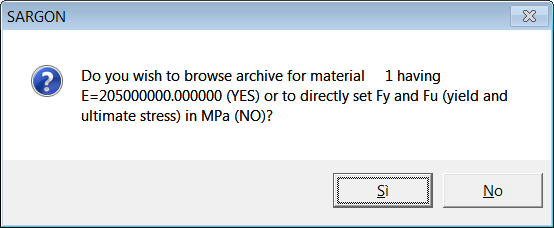
During conversion, as material data extracted to .STD.TXT file by macro lacks info about yield and ultimate stresses, the user is asked to fill the missing data by choosing:
1.Or to assign fy and fu by browsing the Sargon / CSE material archive, to choose one material. That material will just be used to set fy and fu.
2.Or keep all data defined in the conversion file, and just add the yield stress value (fy) and the ultimate stress value (fu) by directly input those values.
This question (see previous figure) is repeated for all materials defined in the model. The material is identified by its number and by its elastic modulus.
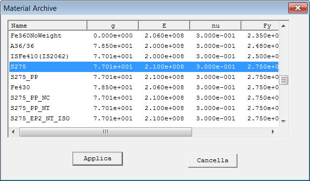
If the answer is Yes, then the following dialogue appears:
The user will browse through the archive and choose the material wished. The units of measurement used are those defined in the conversion file: [kN, meter] if metric units are used in the STAAD file, or [kips, inch] if imperial units are used int he STAAD file. However here no data must be input: you just have to choose a row and press Apply (Applica).
If the answer is "No" then the user must just fill the edit boxes referring to yield stress and ultimate stress, in the next dialog. This must be done using the units of measurement defined in the conversion file: [kN, meter] if metric units are used in the STAAD file, or [kips, inch] if imperial units are used int he STAAD file.
It is of course of the utmost importance that these data are filled correctly.
Converting supports
No skewed support is presently imported. Elastic supports are converted into translational or rotational springs in the Sargon / CSE environment.
Converting members
Members are mapped to beam elements in the Sargon CSE working environment. Offsets and end releases (0 or 1) are converted and assigned to elements according to those defined in the STAAD PRO working environment. No elastic release or partial release is presently imported. However, release elastic constants are written in the .STD.TXT file for future use.
As member end forces are directly read from results this will not affect stress state in using STAAD imported model in CSE.
If, on the other hand, the model has been imported into Sargon, these elastic releases will have to be re-assigned in view of a perfect match between the original and imported model.
Converting plates.
A constant thickness is assumed for plate elements. This constant thickness is got by a simple average of the 3 or 4 node-thicknesses of the element as defined in STAAD PRO. No orthotropic material assigned to plate elements is imported or assigned.
Converting solids
Due to the lack of documentation about solid elements in Open Staad reference manual, no material is assigned to solid elements, however their connectivity is read and assigned to solid elements in the Sargon / CSE working environment.
Converting members with the Truss, or NoTension, or NoCompression, or Cable flag
These elements are converted as beam members with properly auto assigned end releases. The following end releases are assigned automatically:
First Extreme: RxRyRz (R1R2R3) all rotations
Second Extreme: RyRz (R2R3) all rotations but torsional
In fact, in STAAD PRO elements with the flag Truss can still have shears inside. So they are mapped to beams properly released. The joist flag is not managed presently.
Converting primary load cases
Primary load cases are converted and added to Sargon / CSE model. The name of the primary load case is retained. The primary load case kind is converted according to the following rules.
Code STAAD Sargon / CSE
0 Dead Dead
1 Live Live
2 Roof live Live
3 Wind Wind
4 Seismic Seismic modal
5 Snow Snow
6 Fluids Live
7 Soil Live
8 Rain Live
9 Ponding Live
10 Dust Live
11 Traffic Live
12 Temp Temperature
13 Imperfection Live
14 Accidental Live
15 Flood Live
16 Ice Live
17 Wind ice Live
18 Crane hook Live
19 Mass Live
20 Gravity Gravity
21 Push Live
22 None Live
Converting load case combinations
What is named "load case combination" in the STAAD working environment, is simply named "combination" in the Sargon or CSE working environment.
In STAAD combinations do not have name, so they are named in Sargon / CSE according to their progressive number. Load factors are read from file .STD.TXT and assigned to combinations in Sargon / CSE model.
Results in combinations are got by Sargon / CSE at runtime, by linearly combining effects of load cases.
In Sargon / CSE combinations may be selected or not. Once imported in the new model, all combinations are selected by definition.
Converting single actions
The following single actions are converted and assigned in the new Sargon / CSE model:
1.Nodal forces and nodal moments.
2.Uniformly distributed forces over member elements (including d1 and d2 data, but not d3 which is assumed null).
3.Uniformly distributed moments over member elements (including d1 and d2 data, but not d3 which is assumed null).
4.Concentrated forces applied to member elements (including d1, but not d2 which is assumed null).
5.Concentrated moments applied to member elements (including d1, but not d2 which is assumed null).
6.Trapezoidal loads (forces per unit length) applied to member elements.
7.Linear varying loads (forces per unit length) applied to member elements
OpenSTAAD.Load functions "GetXXX" referenced in technical guide are unfortunately not enough to extract all data referring to loads applied.
So self weight is not converted due to a lack in Open Staad documentation.
Temperature loads are not converted nor assigned.
Element pressures are not converted and assigned.
The only loads which can be imported are those clearly referenced in the Open Staad documentation, for OpenSTAAD.Load object. While AddXXX functions are many, GetXXX functions are quite fewer.
Converting connection codes
Connection codes are not supported by STAAD, and it was not possible to use special rules to make Sargon/CSE able to assign needed connection codes (as done for SAP2000, for example, where conventional groups define connection codes on beam elements extremes). For this reason, user possibly needs to define connection codes in Sargon or CSE after the model has been imported from STAAD and before JNODES are searched for. If end releases are left unchanged and only connection codes are added, this operation does not imply a loss of results as no true modification is applied to analytical model. So imported results will be still available after connection codes definition. We recall here briefly that connection codes are useful when more elements meet in a node without any end release: connection codes will mark the elements which will be interrupted and connected, while element with no connection code will remain unmodified and will therefore be the "master" of the connection.
Converting the results (post-processing)
As already mentioned if results of the STAAD analysis are available, the import routine can create the binary files with the results in the Sargon/ CSE format. The following are imported:
1.All displacements of all nodes in all load cases and combinations (file MODEL.DDB).
2.All constraint reactions of all nodes in all load cases and combinations (file MODEL.RDB).
3.All internal forces at beams extremes in all load cases and combinations (file MODEL.SDB).
4.Currently, the stresses for two-dimensional and solid elements are not imported and are therefore null.
IMPORTARE .SR3 (QUALSIASI PROGRAMMA)
Se si dispone di un programma agli elementi finiti che supporta il formato Open Sargon, si dovranno esportare i file seguenti, quindi, si dovrà importare il file .sr3 in CSE.
•Un file binario .sr3 che descrive il modello fem
•Un file binario .ddb che descrive gli spostamenti nodali calcolati
•Un file binario .sdb che descrive gli sforzi e le azioni interne calcolati
•Un file binario .rdb che descrive le reazioni vincolari calcolate
Se si utilizza un programma che non supporta il formato Open Sargon, si può fare richiesta al produttore del software in questione di implementarlo, secondo i criteri reperibili all’indirizzo internet http://www.steelchecks.com/CONNECTIONS/interface.asp, oppure implementarlo autonomamente secondo gli stessi criteri. Poiché per CSE sarebbe necessario un interfacciamento diverso per ogni programma agli elementi finiti, la soluzione è stata quella di rendere disponibile un formato aperto attraverso il quale i dati di un modello fem fatto con un programma qualsiasi possono essere convertiti in un formato leggibile da CSE.
IMPORTARE .SR4 (QUALSIASI PROGRAMMA)
Se si dispone di un programma agli elementi finiti che supporta il formato Open Sargon, si dovrà esportare il file seguente, quindi, si dovrà importare il file .sr4 in CSE.
•Un file ASCII .sr4 che descrive il modello fem e la risposta in termini di spostamenti e azion interne
Se si utilizza un programma che non supporta il formato Open Sargon, si può fare richiesta al produttore del software in questione di implementarlo, secondo i criteri reperibili all’indirizzo internet http://www.steelchecks.com/CONNECTIONS/interface.asp, oppure implementarlo autonomamente secondo gli stessi criteri. Poiché per CSE sarebbe necessario un interfacciamento diverso per ogni programma agli elementi finiti, la soluzione è stata quella di rendere disponibile un formato aperto attraverso il quale i dati di un modello fem fatto con un programma qualsiasi possono essere convertiti in un formato leggibile da CSE.
Il formato ASCII .SR4 è molto semplice da scrivere e quindi rappresenta il modo più semplice per creare una interfaccia con CSE. Qui di seguito un semplice esempio di tale file. Si rimanda al link già indicato per ulteriori approfondimenti su questo formato.
JOINT COORDINATES
4
1 0.000000e+000 0.000000e+000 0.000000e+000
2 0.000000e+000 0.000000e+000 4.000000e+003
3 6.000000e+003 0.000000e+000 4.000000e+003
4 6.000000e+003 0.000000e+000 0.000000e+000
JOINT CONSTRAINTS
1 1 1 1 1 1 1
2 0 0 0 0 0 0
3 0 0 0 0 0 0
4 1 1 1 1 1 1
MATERIALS
1
1 2.099997e+005 3.000000e-001 7.700850e-005 1.200000e-005 "S235"
CROSS SECTIONS
2
1 0 "HE180B"
2 0 "IPE220"
BEAMS
3
1 1 2 1 1 0.000000e+000 1.000000e+000 0.000000e+000
2 2 3 2 1 0.000000e+000 1.000000e+000 0.000000e+000
3 4 3 1 1 0.000000e+000 1.000000e+000 0.000000e+000
BEAM RELEASE
1 0 0 0 0 0 0 0 0 0 0 0 0
2 0 0 0 0 0 0 0 0 0 0 0 0
3 0 0 0 0 0 0 0 0 0 0 0 0
BEAM CONNECTION CODES
1 0 0 0 0
2 1 1 0 0
3 0 0 0 0
LOAD CASES
2
1 2 "LIVE"
NODAL FORCES
0
BEAM CONCENTRATED FORCES
0
BEAM UNIFORM LOADS
1
2 1 0 0.000000e+000 0.000000e+000 -1.200000e+001
BEAM LINEAR LOADS
0
BEAM GENERAL LINEAR LOADS
0
ELEMENT TEMPERATURE LOADS
0
2 4 "Wind +X"
NODAL FORCES
1
2 1 9.810000e+003 0.000000e+000 0.000000e+000
BEAM CONCENTRATED FORCES
0
BEAM UNIFORM LOADS
0
BEAM LINEAR LOADS
0
BEAM GENERAL LINEAR LOADS
0
ELEMENT TEMPERATURE LOADS
0
COMBINATIONS
2
0 "Combi 1: (1,5 ; 0)"
1 1.500000e+000
2 0.000000e+000
0 "Combi 2: (1,5; 1,05)"
1 1.500000e+000
2 1.050000e+000
DISPLACEMENTS
1 1 0.000000e+000 0.000000e+000 0.000000e+000 0.000000e+000 0.000000e+000 0.000000e+000
1 2 4.556698e-002 0.000000e+000 -1.050905e-001 0.000000e+000 3.723036e-003 0.000000e+000
1 3 -4.556698e-002 0.000000e+000 -1.050905e-001 0.000000e+000 -3.723036e-003 0.000000e+000
1 4 0.000000e+000 0.000000e+000 0.000000e+000 0.000000e+000 0.000000e+000 0.000000e+000
2 1 0.000000e+000 0.000000e+000 0.000000e+000 0.000000e+000 0.000000e+000 0.000000e+000
2 2 5.974094e+000 0.000000e+000 7.057373e-003 0.000000e+000 1.277617e-003 0.000000e+000
2 3 5.932202e+000 0.000000e+000 -7.057373e-003 0.000000e+000 1.265200e-003 0.000000e+000
2 4 0.000000e+000 0.000000e+000 0.000000e+000 0.000000e+000 0.000000e+000 0.000000e+000
REACTIONS
1 1 1.064398e+004 -0.000000e+000 3.600000e+004 -0.000000e+000 1.379966e+007 -0.000000e+000
1 2 -0.000000e+000 -0.000000e+000 5.002221e-012 -0.000000e+000 5.587935e-009 -0.000000e+000
1 3 1.818989e-012 -0.000000e+000 -0.000000e+000 -0.000000e+000 -1.117587e-008 -0.000000e+000
1 4 -1.064398e+004 -0.000000e+000 3.600000e+004 -0.000000e+000 -1.379966e+007 -0.000000e+000
2 1 -4.917267e+003 -0.000000e+000 -2.417588e+003 -0.000000e+000 -1.240426e+007 -0.000000e+000
2 2 -0.000000e+000 -0.000000e+000 4.547474e-013 -0.000000e+000 1.862645e-009 -0.000000e+000
2 3 -1.955414e-011 -0.000000e+000 -0.000000e+000 -0.000000e+000 1.862645e-009 -0.000000e+000
2 4 -4.892733e+003 -0.000000e+000 2.417588e+003 -0.000000e+000 -1.233021e+007 -0.000000e+000
ELEMENT INTERNAL FORCES
BEAM
1 1 1 3.600000e+004 0.000000e+000 -1.064398e+004 0.000000e+000 1.379966e+007 0.000000e+000
1 1 2 -3.600000e+004 0.000000e+000 1.064398e+004 0.000000e+000 2.877625e+007 0.000000e+000
1 2 1 1.064398e+004 0.000000e+000 3.600000e+004 0.000000e+000 -2.877625e+007 0.000000e+000
1 2 2 -1.064398e+004 0.000000e+000 3.600000e+004 0.000000e+000 2.877625e+007 0.000000e+000
1 3 1 3.600000e+004 0.000000e+000 1.064398e+004 0.000000e+000 -1.379966e+007 0.000000e+000
1 3 2 -3.600000e+004 0.000000e+000 -1.064398e+004 0.000000e+000 -2.877625e+007 0.000000e+000
2 1 1 -2.417588e+003 0.000000e+000 4.917267e+003 0.000000e+000 -1.240426e+007 0.000000e+000
2 1 2 2.417588e+003 0.000000e+000 -4.917267e+003 0.000000e+000 -7.264810e+006 0.000000e+000
2 2 1 4.892733e+003 0.000000e+000 -2.417588e+003 0.000000e+000 7.264810e+006 0.000000e+000
2 2 2 -4.892733e+003 0.000000e+000 2.417588e+003 0.000000e+000 7.240718e+006 0.000000e+000
2 3 1 2.417588e+003 0.000000e+000 4.892733e+003 0.000000e+000 -1.233021e+007 0.000000e+000
2 3 2 -2.417588e+003 0.000000e+000 -4.892733e+003 0.000000e+000 -7.240718e+006 0.000000e+000
END FILE
IMPORTING .R3D FILES (RISA3D© models)
versions from July 2013 onwards
[questa sezione è in inglese]
Sargon/ CSE offers the ability to import models prepared in RISA3D©. However, as RISA3D uses "physical elements" which are not standard finite elements, Sargon/ CSE cannot also import and convert the results of the analysis carried out in RISA3D©. Physical elements in RISA3D, if detected, are automatically splint into proper finite elements.
General introduction
The interface between Sargon, CSE and RISA3D can be implemented by asking Sargon or CSE to read a .R3D model provided in a given folder.
The RISA3D model has file extension .R3D.
The following cards are read into Sargon/CSE:
[UNITS]
[.SOLUTION_PARAMETERS] "g" used to decide whether X, Y or Z axis is up. In Sargon/CSE Z is always up.
[MATERIAL_PROPERTIES]
[.GENERAL_MATERIAL]
[.HR_STEEL_MATERIAL]
[.CF_STEEL_MATERIAL]
[.WOOD_MATERIAL]
[.CONCRETE_MATERIAL]
[.ALUMINUM_MATERIAL]
[SECTION_SETS]
[.HR_STEEL_SECTION_SETS]
[.CF_STEEL_SECTION_SETS]
[.WOOD_SECTION_SETS]
[.CONCRETE_SECTION_SETS]
[.ALUMINUM_SECTION_SETS]
[.GENERAL_SECTION_SETS]
[NODES]
[BOUNDARY_CONDITIONS]
[SHAPES_LIST]
[MEMBERS]
[.MEMBERS_MAIN_DATA]
[PLATES]
[SOLIDS]
[BASIC_LOAD_CASES]
[NODE_LOADS]
[POINT_LOADS]
[SURFACE_LOADS]
[DIRECT_DISTRIBUTED_LOADS]
The model read from the R3D file will probably need addition of further information which it has not been possible to directly convert into Sargon/CSE environment. Models created by importing R3D files should be carefully reviewed in order to check that the conversion has worked successfully.
Some specific aspects of the main issues encountered when writing the conversion procedure are discussed in more detail below.
Converting cross-sections
Before opening and reading the model which is to be imported, the conversion routine reads and imports the cross-sections in order to establish a suitable correspondence between the cross-sections in Sargon/CSE and those in RISA3D.
The mapping file between the CSE and RISA3D cross-sections is called "WSR_R3D_SHPCVT.TXT" and can be found in the CSE installation folder. This file should also be edited by the user in order to add new entries, when needed. This file will be used when a RISA3D model is imported into CSE. This file, known as the "mapping file", is usually the same for Sargon and CSE, and is structured as shown below.
$
$
IPE 100 IPE100
IPE 120 IPE120
IPE 140 IPE140
IPE R 140 IPE140R
IPE 160 IPE160
...
The first column lists the names of the sections in the Sargon/CSE environment. The second column lists the corresponding section names in Sap2000. A section is identified by its name. If the name "beta" in Sap 2000 corresponds to the name "alpha" in Sargon/CSE, then the cross-section "alpha" will be mapped to "beta". To find out the properties of the cross-section "alpha", the program must open an archive of cross-sections of type .SMA (an .SMA file); in particular:
•if Sargon is in use, this will be the file "sargon.sma" in the Sargon program folder;
•if CSE is being used, the file is "cse.sma" in the CSE program folder.
If the first line of the mapping file contains a "$" or "\\" symbol that means it is a comment line.
The first 18 characters of the names are used for matching purposes. For two names to be matched, each of these 18 characters must be identical.
The conversion routine works according to the following detailed rules:
1-The cross-sections in the .SMA file relevant to the program in use (Sargon or CSE) are read.
2-The entire conversion file is read into memory with its two columns of names.
3-The cross-sections in the RISA3D model are read and then transformed into Sargon/CSE-type sections following the procedure below.
a- If a conversion is found between the name of the cross-section used in RISA3D model, and one entry of the second column of the mapping file, then the Sargon/CSE cross section in the first column of the proper row of the mapping file will be used.
b- If a conversion is not found and the cross section is of the types ("b" shape type in [SHAPES-LIST]): 1 (rolled I or H); 2 (rectangular hollow section, or tube); 3 (pipe); 4 (parallel flange channel); 5 (Tee rolled cross-section); 6 (double L cross section); 7 (angle); 8 (rectangular cross section); 9 (solid round); 200 (cold formed C); 201 (lipped cold formed C); 202 or 203 (Z cold formed); 251 (pipe); 252 (L cold formed); then the user will be prompted with a specific dialog in order to enter the dimensions of the cross section.
c- If a conversion is not found and the cross section does not belong to any of the previously listed cross-section types, then a dummy rectangular cross section is considered. The user may avoid such unwanted behavior by: i) adding the needed cross section to the Sargon/CSE database by using Samba, if this cross section is not available; ii) adding a new row to the mapping file with the Sargon/CSE archive cross-section name in the first column, and the RISA3D cross-section name in the second column. Otherwise, to save time, cross-section assignment may be re-done in the Sargon/CSE environment.
The conversion file is easy to manage and the user can add any lines they require.
It is as well to note that any user can always ensure that a cross-section in RISA3D is converted correctly to a cross-section in Sargon/ CSE, simply checking that the desired cross-section is in the .SMA archive and that the Sargon/CSE-RISA3D mapping between the names of the two sections is available in the mapping file. Once carried out, the work will of course apply every time those sections, special or otherwise, are used in any model in the future.
When installing upgrades, in order to avoid overwriting your mapping files and SMA archives, it is advisable to take a backup copy of both the mapping file and the SMA file.
Converting materials
Wood material is read with dummy values: it may later be modified according to real needs in Sargon/CSE environment. As not all the needed information is printed in R3D file (for instance yield stress and ultimate stress is not written for all materials), material data should be carefully revised once the file has been imported.
Converting loads, load cases and combinations
The following possible loads are imported into Sargon/ CSE:
•Nodal forces
•Member point loads (member only), both forces and couples, both local and global reference.
•Distributed loads (temperature, forces or couples) on members, in the global or local reference system, also projected.
•Surface loads, which are converted into nodal loads
Basic load cases are read into Sargon/CSE as they are defined in RISA3D. If a load case has gravity multipliers these will be correctly read and the relevant individual loads will be applied to elements in Sargon/CSE. The following mapping between load types has been set up:
RISA3D (load category "h" in [BASIC_LOAD_CASES]) |
Sargon/CSE |
0 |
LIVE |
1 |
DEAD |
2 |
LIVE |
3 |
EARTHQUAKE |
4 |
WIND |
5 |
SNOW |
6 |
LIVE |
7 |
LIVE |
other |
LIVE |
As results are not read from RISA3D no combination information is presently converted.
Converting elements
Not all the elements defined in RISA3D can be imported into Sargon/ CSE. The following element data are not imported:
- footings
- walls
- diaphragms
It is assumed that relevant walls are modeled via plate elements, while footings will later be modeled in CSE by using constraint blocks.
MEMBERS are read with end releases and axial offsets. No member design parameter, or member supplemental data is read, as it is not used as such in Sargon/CSE programs.
PLATE elements are read but not the wall parts.
Converting connection codes
Within Sargon/CSE, the connection code is used to indicate members which, although statically continuous with the node, must be considered as interrupted from a constructional point of view. Frame elements possessing any kind of end-release are automatically considered interrupted, hence there is no need for any connection code. There is, however, the problem of those elements which, despite having no end-release, must still be considered interrupted for the purposes of finding the equal jnodes and renodes in CSE. As there is no coding for this information in RISA3D, connection codes will have to be applied in Sargon/CSE environment before the jnode search is asked for.
Converting the results (post-processing)
The results of the analysis carried out in RISA3D are currently not available in CSE/Sargon, as:
1.Physical elements in RISA3D cannot be mapped into finite elements in Sargon / CSE. No proper nodal connection between physical elements and secondary elements is available in RISA3D.
2.No output file with known format is available with the internal forces computed by RISA3D. However, such internal forces, may easily be got by pasting tables from EXCEL into CSE, when needed, or by using special tools to define load levels acting to detach slave members from the master, in CSE.
3.
IMPORTARE FILE .MCT (modelli MIDAS© )
versioni dal Luglio 2013
Sargon/ CSE dà la possibilità di importare modelli preparati in MIDAS©. Così come può importare il modello, Sargon/ CSE può anche importare e convertire i risultati dell'analisi eseguita in MIDAS©. L'interfaccia tra Sargon, CSE e MIDAS© è stata sviluppata in accordo con Simulsoft, il distributore spagnolo di MIDAS.
Introduzione generale
L'interfaccia tra Sargon, CSE e MIDAS può essere realizzata chiedendo a Sargon /CSE di leggere un file .MCT disponibile in una certa cartella.
Dato che i modelli gestiti da MIDAS contengono molte più informazioni di quelle necessarie a Sargon /CSE, molte schede del file MCT non vengono lette. L'interfacca sarà migliorata in modo da poter leggere più schede nelle future versioni.
Attualmente vengono lette e convertite le seguenti schede del file MCT:
*UNIT
*ENDDATA
*NODE
*ELEMENT
*MATERIAL
*PLASTIC-MATL
*SECTION (DBUSER)
*THICKNESS
*CONSTRAINT
*SPRING
*FRAME-RLS
*OFFSET
*STLDCASE
*GROUP
*USE-STLD
*CONLOAD
*BEAMLOAD
*ELTEMPER
*LOADCOMB
Se l'utente decide di importare i risultati di MIDAS all'interno di Sargon / CSE, la routine di conversione:
1.Creerà un file binario .DDB contenente gli spostamenti di tutti i nodi in tutti i casi di carico;
2.Creerà un file binario .SDB contenente le azioni interne nelle travi e nelle bielle in tutti i casi di carico;
3.Creerà un file binario .RDB contenente le reazioni vincolari di tutti i nodi in tutti i casi di carico (0 se il nodo non è vincolato);
4.Marcherà il modello come "risolto" per fare in modo che i risultati siano accessibili nelle fasi del lavoro successive alla importazione.
Alcuni specifici aspetti dei principali temi affrontati quando si è scritta la procedura di conversione sono discussi in maggior dettaglio qui di seguito.
Conversione delle forme sezionali
Prima di aprire e leggere il modello che deve essere importato, la routine di conversione legge ed importa le forme sezionali al fine di stabilire una opportuna corrispondenza tra le forme sezionali in Sargon/CSE e quelle in MIDAS.
Il file di corrispondenza tra le sezioni in Sargon /CSE e quelle in MIDAS si chiama "WSR_MCT_SHPCVT.TXT" e può essere trovato nella cartella di installazione del programma (CSE o Sargon, a seconda di cosa si stia usando). Questo file sarà usato quando un modello MIDAS è importato dentro Sargon o CSE. Questo file, noto come "file di conversione" è normalmente lo stesso per Sargon e CSE, ed è strutturato come mostrato qui sotto.
$
$
IPE 100 IPE100
IPE 120 IPE120
IPE 140 IPE140
IPE R 140 IPE140R
IPE 160 IPE160
...
La prima colonna lista i nomi delle sezioni nell'ambiente Sargon / CSE. La seconda colonna lista le corrispondenti sezioni in MIDAS. Una sezione è identificata dal suo nome. Se il nome "beta" in MIDAS corrisponde al nome "alfa" in Sargon/CSE, allora la forma sezionale "alfa" sarà fatta corrispondere a "beta". Per trovare le proprietà della sezione "alfa" il programma deve aprire un archivio di sezioni del tipo .SMA (un file .SMA); in particolare:
•se si usa Sargon, tale file sarà il file "sargon.sma" nella cartella di installazione del programma Sargon;
•se si usa CSE, il file è il file "CSE.SMA" contenuto nella cartella di installazione di CSE.
Se il primo carattere di una generica linea del file di conversione è un "$" o un "\\" ciò vuol dire che quella riga è un commento.
Per stabilire la corrispondenza tra i nomi vengono usati i primi 18 caratteri. Perché due nomi vengano considerati identici tutti e 18 i caratteri devono essere eguali.
La routine di conversione funziona in accordo a queste regole di dettaglio:
1.Le forme sezionali nel file .SMA pertinente al programma in uso (Sargon o CSE) vengono lette..
2.L'intero file di corrispondenza è letto in memoria con le sue due colonne di nomi.
3.Le forme sezionali nel modello MIDAS sono lette e trasformate in forme sezionali dell'ambiente Sargon / CSE in accordo alle regole seguenti.
a.sezioni DBUSER.
i.Se il primo campo di [DATA] è 1, allora il campo SNAME è usato per cercare la sezione nel file di corrispondenza. Se la sezione è trovata, allora sarà usata la pertinente sezione corrispondente. Se la sezione non è trovata, il simbolo SHAPE è utilizzato al fine di chiedere all'utente le dimensioni pertinenti della sezione del tipo appropriato, in accordo alle seguenti corrispondenze: "H", sezioni laminate a I o H; "B", sezioni RHS; "P", tubi circolari; "L" angolari; "C" C a lati paralleli; "T" T con spigoli vivi; "2L" doppi angolari; "2C" doppi C ][; "SB" rettangolari; "SR" circolari pienebar; "CC" C formate a freddo; altrii simboli: non riconosciuta. Se la sezione non è riconosciuta viene impiegata una sezione rettangolare fittizia.
ii.Se il primo campo di [DATA] è 2, allora le dimensioni della sezione sono lette direttamente dalla scheda, per le forme sezionali "H", "B", "P", "L", "C", "T", "2L", "2C", "SB", "SR", "CC". Non viene chiesto alcun dato all'utente, le sezioni sono lette direttamente e convertite. Possibili problemi nel definire una forma sezionale daranno luogo alla aggiunta di una sezione fittizia denominata "DUMMY".
Il file di conversione è facile da modificare e gli utenti possono aggiungere le linee di cui hanno bisogno.
E' bene notare che ogni utente può sempre assicurarsi che una forma sezionale in MIDAS sia convertita correttamente in una forma sezionale nell'ambiente Sargon/ CSE, semplicemente verificando che la sezione desiderata sia nel file .SMA e che la corrispondenza tra la sezione in Sargon / CSE e in MIDAS sia disponibile all'interno del file di conversione. Una volta condotto a termine, il lavoro sarà ovviamente disponibile tutte le volte che quelle sezioni verranno impiegate in qualche modello, indipendentemente dal loro tipo .
Quando si installano gli aggiornamenti, al fine di evitare la sovrascrittura del proprio file di conversione e dei propri archivi .SMA, è consigliabile eseguire un back up sia del file di conversione sia del file .SMA con gli archivi delle sezioni.
Conversione degli spessori
L'unico tipo di spessore gestito dall'interfaccia è il tipo "VALUE". Gli spessori "STIFFENED" ("irrigiditi") non vengono letti. Se viene trovato uno spessore "STIFFENED" l'esecuzione si arresta.
Conversione dei materiali
Se è definita una parte non lineare di un materiale, allora essa dovrà essere ridefinita impiegando il dialogo standard di Sargon / CSE usato per aggiungere materiali non lineari. La routine di conversione si accorge dell'impiego di un materiale non lineare e chiede all'utente di ridefinire tale parte non lineare usando il dialogo di Sargon / CSE.
Se un materiale ha il tipo "1", ovvero è un materiale standard, l'utente viene richiesto di scegliere se cercare tale materiale standard nell'archivio dei materiali disponnibili in Sargon / CSE o se introdurne le caratteristiche usando il dialogo standard di aggiunta dei materiali.
Se un materiale è di tipo "2", il materiale è isotropo e i suoi dati saranno letti direttamente dal file MCT.
Se un materiale è di tipo "3" è un materiale ortotropo e viene mostrato un messaggio di avviso. L'utente verrà richiesto di introdurre i pertinenti dati del materiale impiegando un modello isotropo.
Conversione di casi di carico e combinazioni
Ogni caso di carico definito in MIDAS implicherà un caso di carico in Sargon /CSE, e sarà usata la seguente tabella di conversione dei tipi.
Caso di Carico (MIDAS) |
Caso di Carico (Sargon / CSE) |
USER |
LIVE |
D |
DEAD |
L |
LIVE |
LR |
LIVE |
W |
WIND |
E |
EARTHQUAKE |
S |
SNOW |
R |
LIVE |
IP |
LIVE |
EP |
LIVE |
WP |
LIVE |
FP |
LIVE |
SF |
LIVE |
B |
LIVE |
CR |
LIVE |
SH |
LIVE |
T |
THERMAL |
PS |
DEAD |
CS |
LIVE |
ER |
LIVE |
IL |
LIVE |
BK |
LIVE |
WL |
WIND |
CF |
LIVE |
CO |
LIVE |
TPG |
LIVE |
MIDAS ha vari tipi di combinazioni (che possono essere combinazioni di casi di carico o di altre combinazioni). Sono importate all'interno di CSE le seguenti combinazioni:
•combinazioni del tipo “lineare additivo”
•combinazioni "SRSS" (+ e -);
Le combinazioni sono aggiunte al Combi Set attivo in Sargon / CSE. Sono lette e decodificate sia le combinazioni che impiegano i casi di carico standard ("ST") sia le combinazioni che impiegano altre combinazioni ("CB").
Conversione di carichi
Sono importati i seguenti possibili carichi:
•Forze nodali
•Momenti nodali
•Carichi distribuiti (forze o coppie) su elementi beam, nel sistema di riferimento globale o locale
•Carichi concentrati (forze or coppie) su elementi beam, nel sistema globale o locale
•Carichi gravitazionali
•Carichi termici
Conversione di elementi
Non tutti gli elementi definiti in MIDAS possono essere importati in Sargon/ CSE e vice-versa.
Qui di seguito viene spiegato quali elementi siano importati e quali no.
1.Elementi beam e truss in MIDAS
a.Sono sempre importati in Sargon / CSE come elementi beam quando il TYPE è BEAM, e come elementi truss quando il tipo è TRUSS, TENSTR o COMPTR.
b.Non viene letto alcun dato aggiuntivo specificamente relativo a elementi TENSTR o COMPTR.
c.Viene letto e convertito sia il metodo che usa un angolo, sia il metodo che usa un punto di riferimento, per decidere l'orientazione dell'elemento.
d.Rigidezze parziali alle estremità vengono definite solo per la modalità di input VALUE (quindi non come rigidezza relativa) e solo per My e Mz.
2.Elementi piani in MIDAS.
a.Questi elementi sono aggiunti come piastre in Sargon / CSE quando TYPE è PLATE, e come elementi membrana quando TYPE è PLSTRS.
b.Essi non sono consiederati se hanno TYPE PLSTRN o AXISYM.
c.Sono tenute in conto sia le piastre sottili che quelle spesse.
3.Elementi solidi in MIDAS. Questi sono convertit in elementi solidi in Sargon/ CSE (tetra, wedge, brick).
4.Gli elementi SPRING in MIDAS sono letti e convertiti in molle in Sargon / CSE quando viene usata la scheda SPRING.
5.Elementi GSPRING in MIDAS. Questi elementi non sono al momento convertiti.
6.Elementi ELASTICLINK in MIDAS. Questi elementi non sono al momento convertiti.
7.Elementi GL-LINK in MIDAS. Questi elementi non sono al momento convertiti.
8.Elementi RIGIDLINK in MIDAS. Questi elementi non sono al momento convertiti.
Conversione di segni di connessione
All'interno di Sargon si fa uso del segno di connessione per indicare membrature che, pur essendo staticamente in continuità sul nodo, devono essere considerate costruttivamente interrotte. Elementi beam che posseggano un qualche tipo di end-release sono considerati automaticamente interrotti, e quindi non è necessario apporre alcun segno di connessione. Il problema invece si pone per quegli elementi che, pur non avendo alcun end-release, devono essere considerati interrotti al fine di ricercare i jnodi eguali ed i renodi in CSE.
Dato che le informazioni "normali" gestite da MIDAS non consentivano di passare esplicitamente questa informazione, si è provveduto a predisporre una opportuna codifica, che, utilizzando il concetto di "gruppo" presente in MIDAS, fosse utile a far passare le informazioni desiderate.
Un elemento frame può avere un segno di connessione ad un estremo, all'altro o a tutti e due. Come già detto, se ad un estremo è presente un end release allora non è necessario aggiungere un segno di connessione perchè è implicito.
In MIDAS si potranno aggiungere i seguenti gruppi:
"BI"
"BJ"
"BIBJ"
Tutti gli elementi beam che appartengono al gruppo "BI" hanno l'estremo "I" con segno di connessione;
Tutti gli elementi beam che appartengono al gruppo "BJ" hanno l'estremo "J" con segno di connessione;
Tutti gli elementi beam che appartengono al gruppo "BIBJ" hanno entrambi gli estremi con segno di connessione.
Gli elementi biella hanno per definizione una interruzione ad entrambi gli estremi e non necessitano di segni di connessione.
Convesione dei risultati (post-processing)
Come già detto, se i risultati dell'analisi condotta con MIDAS sono disponibili, la routine di importazione può creare file binari con i risultati nel formato Sargon/ CSE. Vengono importati i seguenti risultati:
1.Tutti gli spostamenti di tutti i nodi in tutti i casi di carico;
2.Tutte le reazioni vincolari di tutti i nodi vincolati in tutti i casi di carico (riferimento globale);
3.Tutte le azioni interne negli elementi trave e biella, in tutti i casi di carico.
4.Tutte le azioni interne negli elementi molla in tutti i casi di carico.
Al momento, gli sforzi interni agli elementi piani e solidi non vengono importati, e quindi sono considerati nulli.
Alla fine della lettura del modello, il programma chiederà se leggere o no i risultati. Se i risultati non saranno letti, non sarà creato alcun file binario con i risultati, e nessun risultato sarà in seguito disponibile ai fini delle verifiche. Se invece l'utente risponde "sì", allora egli / ella sarà riceverà prima di tutto la richiesta di fornire le unità di misura con cui interpretare i file con i risultati, mediante un opportuno property sheet.
A partire dalla versione 6.32, rilasciata nel maggio 2015, onde evitare i problemi legati al fatto che i dati di interesse vengono scritti in colonne differenti a seconda delle diverse versioni di MIDAS ed a seconda del tipo di analisi eseguita, un opportuno dialogo chiede di specificare il numero di colonna (nel file csv pertinente) che corrisponde ad un certo dato. Nel caso degli spostamenti (6 colonne), delle reazioni vincolari (6 colonne) e delle azioni interne (6 colonne o 2 colonne), va specificata la prima colonna.
La numerazione delle colonne, nel file CSV non considera le colonne vuote, che vengono scartate.
Le colonne da specificare sono.
Per gli spostamenti: nodo, caso di carico e prima colonna degli spostamenti.
Per le reazioni vincolari: nodo, caso di carico e prima colonna delle reazioni.
Per le azioni interne degli elementi trave: elemento, caso di carico, parte ("I" o "J") e prima colonna delle (6) azioni interne.
Per le azioni interne degli elementi biella: elemento, caso di carico e prima colonna delle (2) azioni interne.
Fatto questo l'utente dovrà specificare un certo insieme di file CSV, uno per ognuno dei seguenti insiemi di dati:
•spostamenti nodali;
•reazioni vincolari nodali;
•azioni interne negli elementi trave;
•azioni interne negli elementi biella.
Se anziché secegliere un file viene premuto il tasto CANCEL, in qualsivoglia dei dialoghi che chiedono il nome del file che via via si presentano, i corrispondenti risultati verranno tutti posti eguali a zero, e sarà proposta la richiesta del file successivo.
Per poter leggere correttamente i file CSV l'utente deve aver convertito i file XLS, XSLX ottenuti da MIDAS, in file CSV, mediante l'impiego del comando "Salva In" di EXCELTM , e selezionando il formato di file opportuno, che è "CSV (MS DOS)".
I file CSV non devono usare la virgola come separatore decimale ma il punto ".". Quindi se EXCEL crea il file di conversione da XLS a CSV impiegando la virgola come separatore decimale, bisogna applicare un Trova e Sostituisci (per esempio editando il file CSV con NOTEPAD, BLOCCO NOTE) a tutto il file sostituendo alle virgole i punti. Il file CSV generato dal comando Salva In usa il punto e virgola ";" come separatore dei campi di una data riga.
Qui di seguito viene fornito un breve esempio di file ottenuto per gli spostamenti, le reazioni, le azioni interne delle travi e le azioni interne delle bielle, usando il comando Salva In di EXCEL. Nelle prime linee create viene trovato anche qualche carattere "NEWLINE" extra (ASCII CODE 10): questi caratteri extra sono correttamente tenuti in conto dal convertitore.
DISPLACEMENTS
;Displacements;;;;;;;;;;;;
;;Node;Load;Stage;Step;Step Order;"DX
(m)";"DY
(m)";"DZ
(m)";"RX
([rad])";"RY
([rad])";"RZ
([rad])";Load Order
;;1;01_pp estructura;;;0;-0.000235;0.000563;-0.001542;0.000732;0.0002;-0.000042;300001
;;2;01_pp estructura;;;0;-0.000131;0.000522;-0.000205;0.000403;0.001152;-0.000019;300001
;;3;01_pp estructura;;;0;0;0;0;0;0;0;300001
;;4;01_pp estructura;;;0;-0.000099;0.000516;-0.000031;0.000114;-0.000026;-0.00005;300001
;;5;01_pp estructura;;;0;-0.000013;0.000526;-0.000353;-0.000314;0.001301;-0.000031;300001
;;6;01_pp estructura;;;0;0.00014;0.000539;-0.000776;0.000033;0.001104;-0.000023;300001
;;7;01_pp estructura;;;0;0.000167;0.000531;-0.000547;0.000278;0.001146;0.000036;300001
Per questo file le corrette impostazioni per le colonne sono (1 per il nodo, 2 per il caso di carico e 4 per gli spostamenti).
REACTIONS
;Reaction(Global);;;;;;;;;;;;
;;Node;Load;Stage;Step;Step Order;"FX
(kN)";"FY
(kN)";"FZ
(kN)";"MX
(kN*m)";"MY
(kN*m)";"MZ
(kN*m)";Load Order
;;3;01_pp estructura;;;0;0.033122;-0.1563;7.051901;0.234921;0.068793;0.000143;300001
;;9;01_pp estructura;;;0;-0.035992;-0.111674;5.523255;0.181268;-0.165302;0.00031;300001
;;14;01_pp estructura;;;0;-0.047094;0.102017;8.226277;-0.149291;-0.251207;-0.000388;300001
;;53;01_pp estructura;;;0;0;-2.209851;0;0;0;0;300001
;;55;01_pp estructura;;;0;0.51302;3.717744;92.398884;-4.483324;2.742602;0.004236;300001
;;65;01_pp estructura;;;0;-2.951695;-3.803535;103.941943;20.945472;-6.583367;0.003907;300001
;;70;01_pp estructura;;;0;-0.000001;-1.435116;0;0;0;0;300001
;;120;01_pp estructura;;;0;-0.000001;-2.139589;0;0;0;0;300001
Per questo file le corrette impostazioni per le colonne sono (1 per il nodo, 2 per il caso di carico e 4 per le reazioni).
BEAM FORCES
;Beam Force;;;;;;;;;;;;;;;;;
;;Elem;Load;Stage;Step;Step Order;Part;Part Order;Component;"Axial
(kN)";"Shear-y
(kN)";"Shear-z
(kN)";"Torsion
(kN*m)";"Moment-y
(kN*m)";"Moment-z
(kN*m)";Load Order;Compo Order;Stress
;;50;01_pp estructura;;;0;I[1];0;;-0.04;0;-0.97;0.01;-0.07;0;300001;0;
;;50;01_pp estructura;;;0;J[2];4;;-0.02;0;-1.66;0.01;2.68;0;300001;0;
;;51;01_pp estructura;;;0;I[2];0;;0;0.02;-3;-0.03;2.68;0;300001;0;
;;51;01_pp estructura;;;0;J[4];4;;0;0.02;-3.2;-0.03;4.56;-0.01;300001;0;
;;52;01_pp estructura;;;0;I[3];0;;-7.05;0.16;0.03;0;0.07;0.23;300001;0;
Per questo file le corrette impostazioni per le colonne sono (1 per l'elemento, 2 per il caso di carico, 4 per la parte, e 6 per le azioni interne).
TRUSS FORCES
;Truss Force;;;;;;;;
;;Elem;Load;Stage;Step;Step Order;"Force-I
(kN)";"Force-J
(kN)";Load Order
;;1;01_pp estructura;;;0;5.245034;5.140802;300001
;;2;01_pp estructura;;;0;9.540789;9.313239;300001
;;3;01_pp estructura;;;0;11.555538;11.199402;300001
;;4;01_pp estructura;;;0;7.710519;7.873809;300001
;;5;01_pp estructura;;;0;16.289015;16.036842;300001
;;6;01_pp estructura;;;0;12.001037;11.826999;300001
;;7;01_pp estructura;;;0;23.159878;22.632203;300001
;;8;01_pp estructura;;;0;9.300742;9.073364;300001
Per questo file le corrette impostazioni per le colonne sono (1 per l'elemento, 2 per il caso di carico, 4 per le azioni interne).
Dato che in Sargon /CSE non può essere applicato alcun carico interno agli elementi biella e diretto come l'asse della biella stessa, le forze alle estremità degli elementi biella in Sargon / CSE sono identiche in modulo ed opposte in segno. Quando vengono lette le azioni interne delle bielle dal file CSV (dove si possono trovare, in rari casi, azioni diverse ai due estremi), verranno considerate come forze della biella quelle del secondo estremo.
IMPORTARE FILE .DXF (disegni Autocad© 14)
versioni dal Maggio 2016
Tutte le primitive grafiche "linea" contenute nel file .dxf vengono convertite in elementi trave. L'orientazione viene definita sulla base del numero di colore della linea; se esso è maggiore di 6 deve esistere una primitiva "punto" con lo stesso numero di colore nel file .dxf. Le coordinate di tale punto sono quelle del relativo terzo nodo. I colori (1-2-3-4-5-6) implicano un terzo nodo all'infinito nelle direzioni (+Y, +Z, +X, -Y, -Z, -X), rispettivamente.
Ad ogni layer differente corrisponde un numero differente di gruppo. Il file di CSE conterrà tutti i layer del file .dxf sotto forma di gruppi, il nome dei quali sarà eguale al nome del layer corrispondente. Il numero di gruppi è sempre almeno pari a 10, pertanto se il numero di layer definiti nel file .dxf è inferiore a 10 vi saranno dei gruppi con nome eguale a quello di default.
In fase di impostazione del modello tramite CAD esterno è consigliato definire le unità in cui vengono espresse le dimensioni della struttura. È sufficiente inserire in un qualunque punto del disegno una stringa alfanumerica che indichi l'unità usata @mm, @cm, @m, @in, @ft, @yd. Se CSE non individua nel disegno un'entità con tali caratteristiche, assume che l'unità di lunghezza sia quella corrente al momento del caricamento della struttura.
-----------------------------
C.S.E. - 2001-2018 - Copyright Castalia srl - Milan - Italy - www.castaliaweb.com